What is Inventor?
Inventor is a CAD (computer aided design) program by Autodesk. This program allows users to create 3D renderings of real-world objects. Inventor is used by engineers and designers in order to view a product in its finished form. The models and renderings made in Inventor can be transferred to a software like Makerbot in order to be 3D printed.
Designing the widgets.
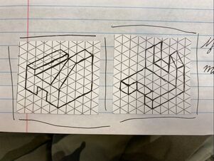
To begin, I sketched the pieces I would be deigning on Illustrator on isometric graphing paper.
After completing sketches of each of the widgets I would design, I opened Illustrator on a desktop computer.
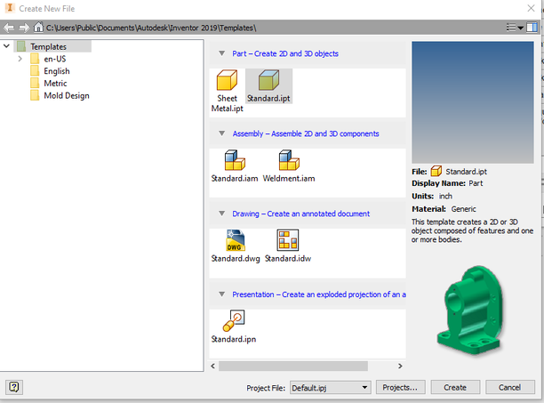
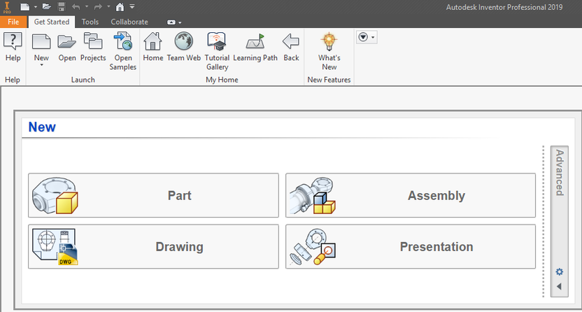
Selecting the "New" option at the top of the screen, I selected the Standard.ipt option and selected the "Create" bar.
After creating a new file, I selected the "Start 2D Sketch" option on the top left corner of the window.
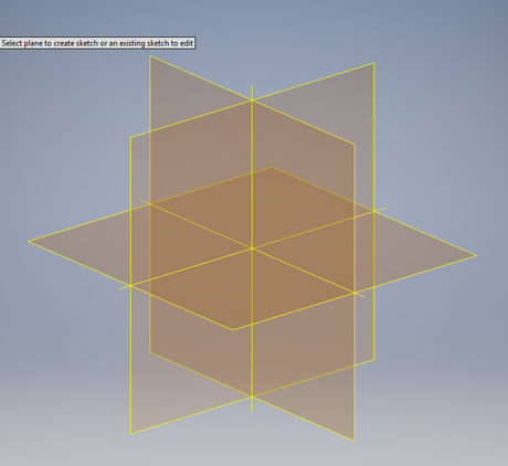
After I selected "Start 2D Sketch", I was taken to this screen. This picture shows the different planes that can be selected to work on. For each of the widgets I chose the XY plane.
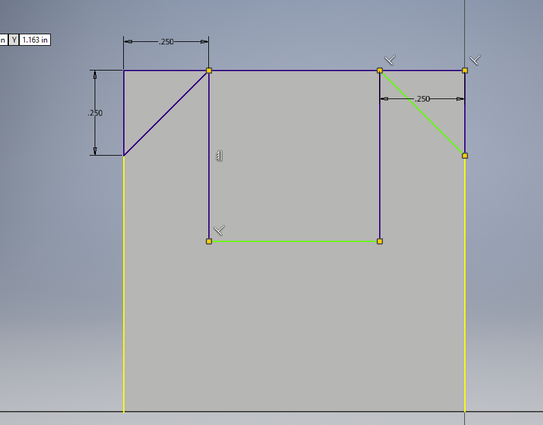
When sketching my widgets out in 2D, I used the line tool to draw the side of the widget out.
Once I had the basic shape of the widget drawn out, I used the "Dimension" tool at the top toolbar to adjust the length of each line, making sure it is proportionate and accurate to my sketch.
After I had drawn out the widget, I selected "Finish Sketch" on the top toolbar and switched to the "3D Model" tab.
Once in the 3D Model tab, I selected "Extrude"
When extruding the sketch, I made sure it was extruded 1 inch out, as that is the width indicated by my sketch.
If I was creating a widget that had an irregular shape (for example, a shape with a part cut out or a slant) I would re-select "Start 2D Sketch" and select the side of the shape I wanted parts to be cut off.
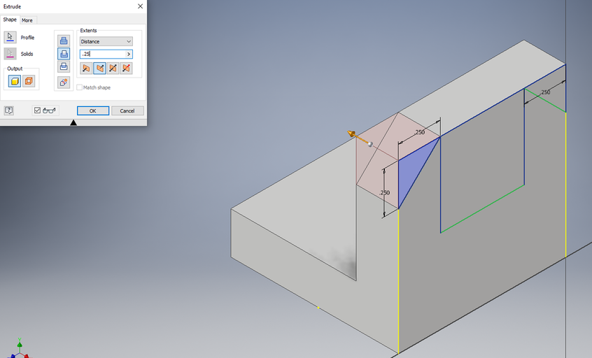
Once the shape was drawn out, I would return to the 3D Model tab and extrude the shape in order to cut a piece out of my widget.
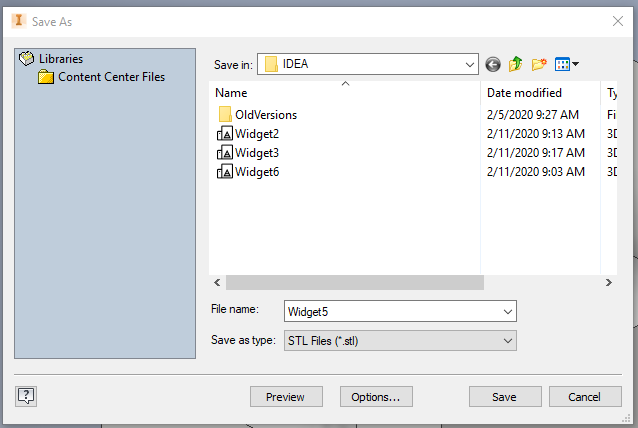
I saved each widget in .stl format by selecting "file" then "export" and selecting "CAD Format". From there I selected the "Save as type" bar and selected "STL Files" from the bar and then saved the file.
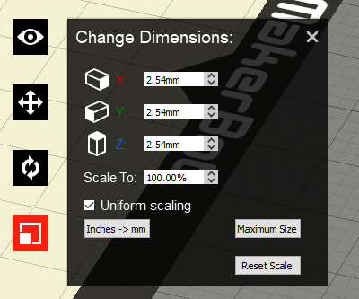
After opening Makerbot and opening the desired file, I adjusted the scale of the widget, making sure that each side measuring 1 inch was 25.4 mm in length.
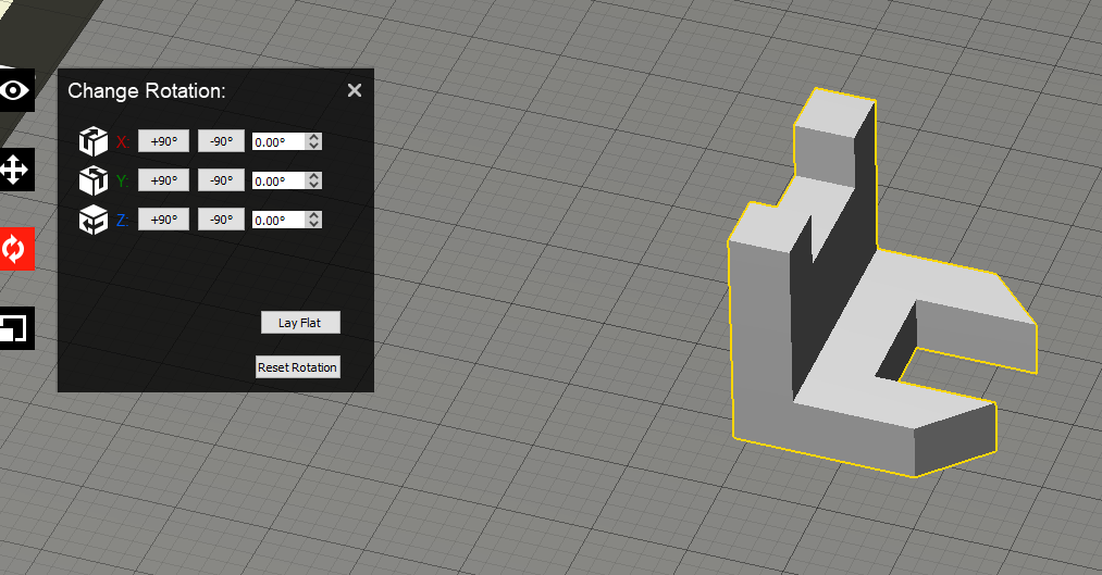
Once the scale was correct, I rotated each widget in a way that it could be printed without supports. I did this by manipulating the X, Y, or Z values in the change rotation tab. Once the widget was in the desired position, I selected "Lay Flat" on the rotation tab to ensure the widget would print flat.
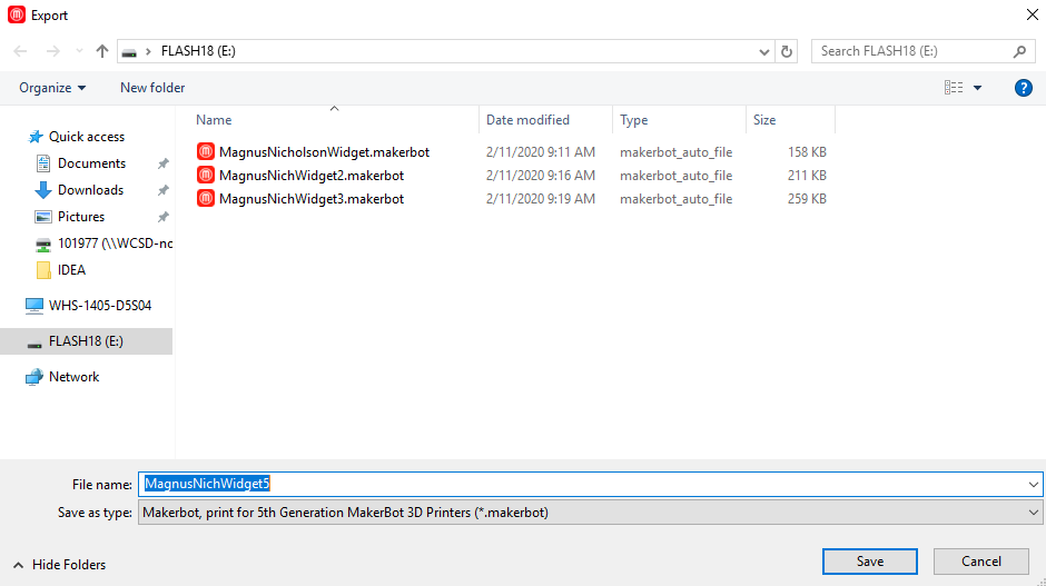
When the widget was adjusted and scaled correctly, I saved the file onto my flash drive.
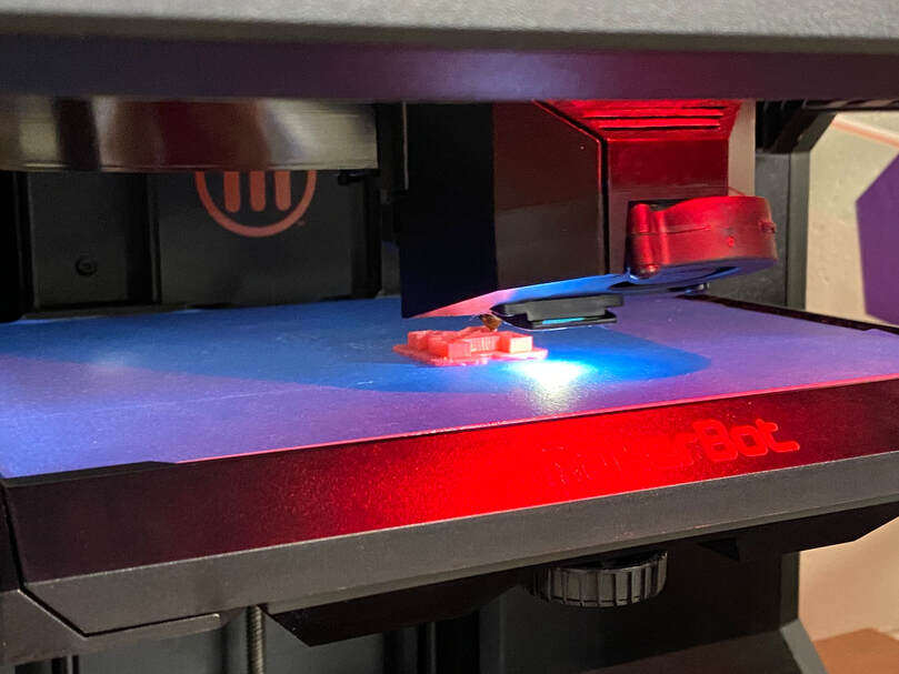
When the file was saved onto my flash drive, I took it down to the 3D printer. Plugging my flash drive into the printer, I selected the file I wanted to print and began to print it.
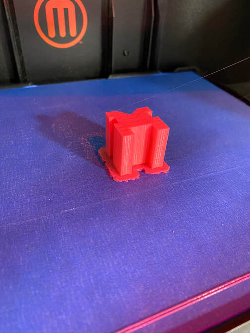
When the widget was finished printing I (carefully) peeled it off the printer bed, disposing of the raft (the printed platform that the widget was built upon).
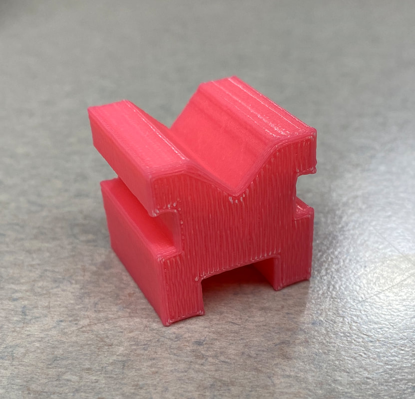
The final product.
What I learned.
Throughout this process, I learned how to use Inventor and what it is used for. Using many different techniques I drew out 6 different widgets on Illustrator. I was also familiarized with the Makerbot software and how to use it to prepare files for 3D printing. After that, I was able to learn how to load a file into a 3D printer and begin the printing process
